
Objective and use case
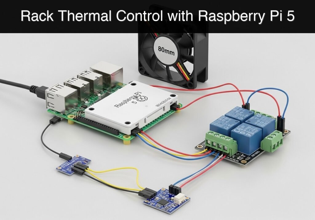
What you’ll build: You will construct a server-rack-thermal-watchdog that monitors ambient temperature and automatically switches on a cooling exhaust fan when a critical thermal threshold (e.g., >40°C) is reached.
Why it matters / Use cases
- Preventing Thermal Throttling: Keeps dense home labs and networking enclosures cool, ensuring servers maintain peak clock speeds without performance degradation.
- Noise Reduction & Energy Efficiency: Eliminates continuous fan noise (0dB when idle) and reduces power consumption by dynamically activating cooling only when the rack demands it, extending fan bearing lifespan.
- Foundational Automation: Introduces hysteresis (e.g., turning ON at 40°C and OFF at 35°C), a crucial control-systems principle that prevents rapid relay toggling and hardware wear near the threshold.
Expected outcome
- A lightweight Python daemon running continuously in the background on a Raspberry Pi 5 with minimal overhead (<1% CPU utilization).
- Automated, reliable GPIO-driven fan control executing a stable thermal hysteresis loop.
Audience: Home lab enthusiasts and system administrators; Level: Beginner to Intermediate
Architecture/flow: Temperature sensor (I2C/1-Wire) reads ambient data → Python daemon evaluates thresholds → Raspberry Pi GPIO triggers relay/PWM → Exhaust fan activates/deactivates.
Educational validation note
Before publication, this case passed the Prometeo automated validation gate with status PASS. The validator checked the code blocks, article structure, copy/paste-safe commands and consistency with the supported device catalog.
Published validation evidence
- Automatic result: PASS.
- Parsed structure: 3 sections, 3 tables and 2 code blocks detected before publication.
- Checked code: 1 Python/py_compile, 1 service/config blocks.
- Supported catalog: the article text was checked against Prometeo’s validation-capable device profiles, and unsupported stacks block publication.
- Report findings: no blocking findings.
This validation confirms syntax and tool compatibility for the published material, but it does not replace physical testing on your exact hardware, wiring and runtime environment.
Educational safety note
This project is a low-voltage educational prototype, not a certified product. Before powering the setup, verify the pinout of your exact Raspberry Pi, never connect 5 V to 3.3 V GPIO pins, disconnect power before changing wiring, and use suitable interfaces or external supplies for sensors, relays, motors or loads.
Conceptual block diagram
High-level view: what enters the system, what each block processes, and what comes out.
Functional architecture
Conceptual flow: local configuration, BLE advertising and phone-side reading.

Prerequisites
- Operating System: Raspberry Pi OS Bookworm (64-bit) installed and updated.
- Software Environment: Python 3.11, standard
aptpackage manager, and basic knowledge of the Linux terminal. - Hardware Interface: I2C must be enabled on the Raspberry Pi (via
sudo raspi-config-> Interface Options -> I2C). - Tools: A small flathead screwdriver for relay terminals, jumper wires (female-to-female and male-to-female), and a breadboard for power distribution.
Materials
To guarantee compatibility and safety, this tutorial uses the exact following device model and components:
* Raspberry Pi 5 + BME280 environmental sensor + 5 V relay module + 80 mm fan
* Power Supply for Fan: A separate 5 V or 12 V DC power adapter matching the voltage rating of your specific 80 mm fan.
* Raspberry Pi Power Supply: Official 27 W USB-C power supply for the Raspberry Pi 5.
Setup/Connection
The hardware setup is divided into two distinct circuits: the low-voltage logic side (sensor and relay control) and the switched power side (the fan).
1. BME280 Sensor Wiring (I2C)
The BME280 communicates with the Raspberry Pi via the I2C protocol.
| BME280 Pin | Raspberry Pi 5 Pin | Physical Pin Number |
|---|---|---|
| VCC / VIN | 3.3V Power | Pin 1 |
| GND | Ground | Pin 9 |
| SDA | GPIO 2 (SDA) | Pin 3 |
| SCL | GPIO 3 (SCL) | Pin 5 |
2. 5 V Relay Module Wiring (Logic Side)
The relay module uses a 5 V logic signal to energize an internal electromagnet, which physically moves a switch.
| Relay Module Pin | Raspberry Pi 5 Pin | Physical Pin Number |
|---|---|---|
| VCC / DC+ | 5V Power | Pin 2 |
| GND / DC- | Ground | Pin 6 |
| IN / SIG | GPIO 17 | Pin 11 |
3. 80 mm Fan Wiring (Switched Power Side)
Design Choice: We wire the fan to the Normally Open (NO) terminal. This means if the Pi is off or the script is not running, the fan remains off. For a true fail-safe where the fan runs if the controller dies, you would use the Normally Closed (NC) terminal.
- Connect the Ground (Negative) wire of your external fan power supply directly to the Ground (Negative) wire of the 80 mm fan.
- Connect the Positive wire of the external fan power supply to the COM (Common) screw terminal on the relay module.
- Connect the Positive wire of the 80 mm fan to the NO (Normally Open) screw terminal on the relay module.
Note: Ensure the grounds of the Raspberry Pi and the external fan power supply are NOT tied together if they are completely isolated systems, as the relay provides mechanical isolation. If powering a 5 V fan directly from the Pi’s 5 V rail (not recommended for large fans due to current spikes), the ground is shared naturally.
Validated Code
The following Python script uses an adapter pattern. If run on a standard computer or a Raspberry Pi lacking the physical sensor libraries, it gracefully falls back to a “mock” mode. The mock mode simulates a rising and falling temperature to validate the hysteresis logic without physical hardware.
thermal_watchdog.py
Public preview of the validated file. The complete source is shown to members and in PDF/Print.
#!/usr/bin/env python3
"""
Server Rack Thermal Watchdog
Monitors ambient temperature and controls a cooling fan via a relay.
Implements hysteresis to prevent relay chatter.
"""

import time
import logging
import sys

logging.basicConfig(
    level=logging.INFO,
    format='%(asctime)s - %(levelname)s - %(message)s',
    handlers=[logging.StreamHandler(sys.stdout)]
)

# ---------------------------------------------------------
# Hardware Abstraction Layer
# ---------------------------------------------------------
try:
    import smbus2
    import bme280
    from gpiozero import OutputDevice
    HARDWARE_AVAILABLE = True
    logging.info("Hardware libraries detected. Running in PHYSICAL mode.")
except ImportError:
    HARDWARE_AVAILABLE = False
    logging.warning("Hardware libraries missing. Running in MOCK mode.")

class BME280Adapter:
    """Adapter for the BME280 I2C sensor."""
    def __init__(self, port=1, address=0x76):
        self.mock_temp = 25.0
        self.mock_direction = 1.0 # 1.0 for heating, -1.0 for cooling

        if HARDWARE_AVAILABLE:
            try:
                self.bus = smbus2.SMBus(port)
                self.address = address
                # Load calibration parameters
                self.calibration_params = bme280.load_calibration_params(self.bus, self.address)
                self.is_mock = False
            except Exception as e:
                logging.error(f"Failed to initialize physical BME280: {e}. Falling back to mock.")
                self.is_mock = True
        else:
            self.is_mock = True

    def read_temperature(self) -> float:
        """Returns temperature in Celsius."""
        if not self.is_mock:
            try:
                data = bme280.sample(self.bus, self.address, self.calibration_params)
                return data.temperature
            except Exception as e:
                logging.error(f"Sensor read error: {e}")
                return 999.0 # Fail-safe high temperature to trigger cooling
        else:
            # Simulate temperature rising to 32C then falling to 24C
            self.mock_temp += (0.5 * self.mock_direction)
            if self.mock_temp >= 32.0:
                self.mock_direction = -1.0
            elif self.mock_temp <= 24.0:
                self.mock_direction = 1.0
            return self.mock_temp
# ...#!/usr/bin/env python3
"""
Server Rack Thermal Watchdog
Monitors ambient temperature and controls a cooling fan via a relay.
Implements hysteresis to prevent relay chatter.
"""
import time
import logging
import sys
logging.basicConfig(
level=logging.INFO,
format='%(asctime)s - %(levelname)s - %(message)s',
handlers=[logging.StreamHandler(sys.stdout)]
)
# ---------------------------------------------------------
# Hardware Abstraction Layer
# ---------------------------------------------------------
try:
import smbus2
import bme280
from gpiozero import OutputDevice
HARDWARE_AVAILABLE = True
logging.info("Hardware libraries detected. Running in PHYSICAL mode.")
except ImportError:
HARDWARE_AVAILABLE = False
logging.warning("Hardware libraries missing. Running in MOCK mode.")
class BME280Adapter:
"""Adapter for the BME280 I2C sensor."""
def __init__(self, port=1, address=0x76):
self.mock_temp = 25.0
self.mock_direction = 1.0 # 1.0 for heating, -1.0 for cooling
if HARDWARE_AVAILABLE:
try:
self.bus = smbus2.SMBus(port)
self.address = address
# Load calibration parameters
self.calibration_params = bme280.load_calibration_params(self.bus, self.address)
self.is_mock = False
except Exception as e:
logging.error(f"Failed to initialize physical BME280: {e}. Falling back to mock.")
self.is_mock = True
else:
self.is_mock = True
def read_temperature(self) -> float:
"""Returns temperature in Celsius."""
if not self.is_mock:
try:
data = bme280.sample(self.bus, self.address, self.calibration_params)
return data.temperature
except Exception as e:
logging.error(f"Sensor read error: {e}")
return 999.0 # Fail-safe high temperature to trigger cooling
else:
# Simulate temperature rising to 32C then falling to 24C
self.mock_temp += (0.5 * self.mock_direction)
if self.mock_temp >= 32.0:
self.mock_direction = -1.0
elif self.mock_temp <= 24.0:
self.mock_direction = 1.0
return self.mock_temp
class RelayAdapter:
    """Adapter for the GPIO Relay module."""
    def __init__(self, pin=17):
        self.state = False
        if HARDWARE_AVAILABLE:
            try:
                # active_high=True means setting to True outputs 3.3V
                self.relay = OutputDevice(pin, active_high=True, initial_value=False)
                self.is_mock = False
            except Exception as e:
                logging.error(f"Failed to initialize physical relay on GPIO {pin}: {e}")
                self.is_mock = True
        else:
            self.is_mock = True

    def turn_on(self):
        if not self.state:
            logging.info("ACTION: Energizing relay (Fan ON)")
            self.state = True
            if not self.is_mock:
                self.relay.on()

    def turn_off(self):
        if self.state:
            logging.info("ACTION: De-energizing relay (Fan OFF)")
            self.state = False
            if not self.is_mock:
                self.relay.off()
# ---------------------------------------------------------
# Main Watchdog Logic
# ---------------------------------------------------------
def main():
# Configuration thresholds
TEMP_THRESHOLD_ON = 30.0 # Turn on fan above 30.0 C
TEMP_THRESHOLD_OFF = 27.0 # Turn off fan below 27.0 C
POLL_INTERVAL = 2.0 # Seconds between readings
logging.info(f"Starting Server Rack Thermal Watchdog.")
logging.info(f"Thresholds -> ON: >{TEMP_THRESHOLD_ON}°C, OFF: <{TEMP_THRESHOLD_OFF}°C")
sensor = BME280Adapter(port=1, address=0x76)
fan_relay = RelayAdapter(pin=17)
try:
while True:
current_temp = sensor.read_temperature()
logging.info(f"Current Temperature: {current_temp:.2f}°C")
# Hysteresis Logic
if current_temp > TEMP_THRESHOLD_ON:
fan_relay.turn_on()
elif current_temp < TEMP_THRESHOLD_OFF:
fan_relay.turn_off()
# If temperature is between OFF and ON thresholds, do nothing (maintain current state)
time.sleep(POLL_INTERVAL)
except KeyboardInterrupt:
logging.info("Watchdog terminated by user. Shutting down safely.")
finally:
# Ensure fan is turned off on script exit (optional, depends on fail-safe preference)
fan_relay.turn_off()
logging.info("Cleanup complete.")
if __name__ == "__main__":
main()
thermal-watchdog.service
To ensure the script runs automatically when the Raspberry Pi boots, we define a systemd service. Save this as thermal-watchdog.service.
[Unit]
Description=Server Rack Thermal Watchdog Service
After=network.target

[Service]
Type=simple
# Adjust the path to match where you cloned/saved the script and venv
ExecStart=/home/pi/watchdog/venv/bin/python /home/pi/watchdog/thermal_watchdog.py
WorkingDirectory=/home/pi/watchdog
StandardOutput=journal
StandardError=journal
Restart=always
RestartSec=5
User=pi

[Install]
WantedBy=multi-user.target
Build/Flash/Run commands
Raspberry Pi OS Bookworm utilizes PEP 668, which restricts global pip installations. Therefore, we use a Python virtual environment.
| Command | Description |
|---|---|
sudo apt-get update && sudo apt-get install -y python3-venv i2c-tools | Installs virtual environment tools and I2C debugging utilities. |
mkdir -p ~/watchdog && cd ~/watchdog | Creates the project directory and navigates into it. |
python3 -m venv venv | Creates an isolated Python virtual environment named venv. |
source venv/bin/activate | Activates the virtual environment. |
pip install smbus2 RPi.bme280 gpiozero | Installs the required hardware interface libraries. |
python3 thermal_watchdog.py | Executes the watchdog script directly in the terminal. |
Service Installation Workflow:
1. Copy the service file: sudo cp thermal-watchdog.service /etc/systemd/system/
2. Reload the systemd daemon: sudo systemctl daemon-reload
3. Enable the service to start on boot: sudo systemctl enable thermal-watchdog.service
4. Start the service immediately: sudo systemctl start thermal-watchdog.service
5. View live logs: journalctl -u thermal-watchdog.service -f
Step-by-step Validation
Use the following checkpoints to ensure your server-rack-thermal-watchdog operates correctly.
- I2C Bus Detection
- Action: Run
i2cdetect -y 1in the terminal. - Observation: A grid of numbers appears.
- Pass condition: The number
76(or77) appears in the grid, confirming the Raspberry Pi 5 successfully communicates with the BME280 sensor.
- Action: Run
- Dry-Run / Mock Validation
- Action: Run the script on a PC or on the Pi before installing
smbus2/gpiozero. - Observation: The console logs “Hardware libraries missing. Running in MOCK mode.” followed by temperatures rising from 25.0°C.
- Pass condition: When the simulated temperature hits 30.5°C, the log outputs “ACTION: Energizing relay (Fan ON)”. When it drops below 27.0°C, it logs “ACTION: De-energizing relay (Fan OFF)”.
- Action: Run the script on a PC or on the Pi before installing
- Physical Sensor Validation
- Action: Run the script on the Pi with the virtual environment activated and hardware connected.
- Observation: The console logs the actual room temperature.
- Pass condition: The temperature reading is stable and matches the approximate ambient temperature of the room.
- Hysteresis Trigger Test
- Action: Pinch the BME280 sensor gently between your fingers to raise its temperature artificially.
- Observation: The logged temperature rises.
- Pass condition: As the temperature crosses 30.0°C, the physical relay produces a distinct “click” sound, an onboard LED on the relay module illuminates
Find this product and/or books on this topic on Amazon
As an Amazon Associate, I earn from qualifying purchases. If you buy through this link, you help keep this project running.
Quick Quiz

Telecommunications Electronics Engineer and Computer Engineer (official degrees in Spain).

